What Is a Specification Model?
When you systematically verify a model against requirements, you generate test cases for each requirement. These tests validate the model, which you can use to generate production code and build confidence that your model satisfies requirements. To create tests that satisfy your requirements, you can construct a specification model. A specification model is an executable entity that you can use to perform requirements-based testing by using Simulink® Design Verifier™ and Requirements Toolbox™.
If you have a set of requirements written in natural language text, you can express them as formal requirements by using a Requirements Table (Requirements Toolbox) block. After defining the requirements in one or more blocks, the blocks and the signals become the specification model. Unlike the model that you want to test, known as the design model, the specification model only specifies what to do, not how to do it.
You can use a specification model to:
Validate the set of requirements in a systematic and quantitative manner.
Automate requirements-based testing.
Identify issues with your design model and requirements.
Use Specification Models in Requirements-Based Testing
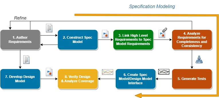
To create and deploy a specification model, follow these steps:
Author the requirements — Write your requirements in natural language text that describes the behavior of the system under design. Author them directly in the Requirements Editor (Requirements Toolbox) or import them. For more information on importing requirements, see Import Requirements from Third-Party Applications (Requirements Toolbox).
Construct the specification model — Design the specification model as a formal representation of the requirements by using at least one Requirements Table block.
Link the requirements — Each requirement that you create in the Requirements Table block creates an equivalent requirement in the Requirements Editor. See Configure Properties of Formal Requirements (Requirements Toolbox). Link the high-level requirements to the formal requirements from the specification model.
Analyze the formal requirements for completeness and consistency — Identifying incomplete and inconsistent requirement sets can be difficult to do manually. The Requirements Table block allows you to automatically analyze the requirements for these issues. See Identify Inconsistent and Incomplete Formal Requirement Sets (Requirements Toolbox).
Generate tests for the specification model — Generate at least one test per requirement that demonstrates its conformance to that requirement. For more information on generating tests, see Generate Test Cases for a Subsystem. Simulink Design Verifier automatically creates test objectives from the requirements defined in Requirements Table blocks.
Interface the specification model with the design model — The specification and design models often do not use identical input and output signals. Convert the test cases that you generate in step 5 by developing an interface between both models.
Develop the design model — Develop the design model by using the requirements. Link the requirements to the design model.
Verify the design and analyze the coverage — Run the tests generated in step 5 on the design model and verify whether the results agree with the specification model and requirements. Generate a coverage report to identify the missing coverage and refine the requirements, if required.
This flow chart illustrates this process.

Construct a Specification Model
Consider the autopilot controller model described in Use Specification Models for Requirements-Based Testing. In this example, you develop requirements that contain logical and temporal conditions that define outputs.
Identify the Specification Model Interface
List the input and output signals for the specification model that are related to the requirements that you want to test. Ignore the signals that the requirements do not specify and that do not affect the tested outputs. In this example, the requirements specify five inputs and two outputs. The specification model input signals are:
Autopilot Engage Switch — A switch that enables or disables the autopilot controller
Heading Engage Switch — A switch that specifies the mode of the autopilot controller when the autopilot switch is engaged
Roll Reference Target Turn Knob — A knob that feeds the desired roll angle value to the autopilot controller
Heading Reference Turn Knob — A knob that gives the set-point value for heading mode
Aircraft Roll Angle — The current roll angle of the aircraft
The output signals are:
Aileron Command — The output to the aileron actuator
Roll Reference Command — The output on the display window that indicates the set-point value for the aileron actuator
Identify Preconditions, Postconditions, and Actions for Each Requirement
For the requirements that you want to verify, transform the textual requirements into logical expressions that can be represented as preconditions, postconditions, and actions. You define formal requirements as a combination of Preconditions, Postconditions, and Actions:
Precondition — A condition that must be true for a specified duration before evaluating the rest of the requirement
Postcondition — A condition that must be true if the associated precondition is true for the specified duration
Action — A behavior that must be performed if the associated precondition is true for the specified duration
You may find that some requirements can use a postcondition or an action interchangeably, or both postconditions and actions. Specify which you want to use based on the configuration of your design model.
For example consider this high level requirement that specifies the modes of the autopilot controller:
The autopilot controller mode is determined by the
                    following:
The autopilot controller is OFF when the autopilot engage
                            switch is not engaged.
The autopilot controller is ROLL_HOLD_MODE when the autopilot engage switch is engaged and the heading engage switch is not engaged.The autopilot controller is HDG_HOLD_MODE when the autopilot engage switch and the heading engage switch are both engaged.
You can write these requirements as these logical expressions:
| Requirement | Precondition | Action |
|---|---|---|
1 | AP_Engage_Switch == false | Mode = Off |
2 | AP_Engage_Switch == true &&
HDG_Engage_Switch == false | Mode = ROLL_HOLD_MODE |
3 | AP_Eng_Switch == true && HDG_Engage_Switch
== true | Mode = HDG_Hold_Mode |
Repeat this process for the remaining requirements.
Identify Design Values Representations in Requirements
Your requirements may specify ranges of values that your design model must satisfy, or you may want to parameterize the values that you evaluate in each requirement. These values cannot always be described easily with literal values. You can use the Requirements Table block to represent values in the expressions as constant or parameter data. See Define Data in Requirements Table Blocks (Requirements Toolbox). You can change data throughout simulation. In addition to assigning numerical values to data, the block supports other data types, such as strings, enumerations, or ranges. Use the representation of values that fits your needs.
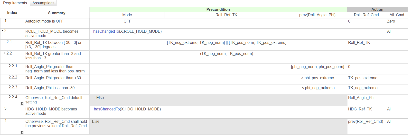
In the autopilot controller model, the requirements specify threshold values for the aircraft roll angle. This graphic illustrates the numerical and verbal equivalents of the thresholds.

Create the Requirements Table Blocks
After identifying the signal representations, values, and the expressions that you want to use in the formal requirements, write the logical expression of the precondition, postconditions, and actions in the Precondition Postcondition, and Action columns for each requirement respectively. If your requirements have children or dependencies, you can include those relationships in the block. See Establish Hierarchy in Requirements Table Blocks (Requirements Toolbox).
Each requirement that you create in the Requirements Table block creates an equivalent requirement in the Requirements Editor. Update additional textual properties of the requirements, such as the description, in the editor. See Configure Properties of Formal Requirements (Requirements Toolbox).
In the autopilot controller model, the specification model includes two
Requirements Table blocks.
AP_Mode_Determination defines the formal requirements for the
autopilot controller mode.

The other Requirements Table block,
Cmd_Determination, describes the desired output of the
aileron command and the roll reference command.

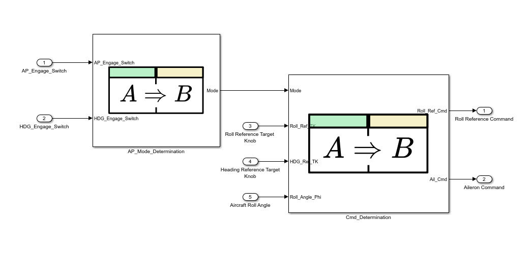
Final Specification Model
After connecting the Requirements Table blocks to the inputs, outputs, and each other, the final specification model is:

Prepare the Specification Model for Test Generation
Simulink Design Verifier automatically creates test objectives from the requirements defined in Requirements Table blocks. If you need to constrain the values of the test objectives, you can specify them either in the signal source, or by including them in the Assumptions table of the block. See Add Assumptions to Requirements (Requirements Toolbox). To prepare the specification model for test generation, set the model coverage objectives. In the Design Verifier tab, in the Prepare section, click Test Generation Settings. In the Configuration Parameters window, expand the Design Verifier list and click Test Generation. Set Model coverage objectives to the option that best captures the desired coverage.
Iterate Through the Steps
As you develop the specification model and test your design model, you typically need to update the requirements, specification model, and design model. This process is iterative. Continue iterating until you reach the desired test outcomes, such desired model outputs and test coverage.
See Also
Requirements Table (Requirements Toolbox)
