Ladder Diagram Integration
Ladder Diagram is a graphical programming language that you use to develop software for programmable logic controllers (PLCs). It is one of the languages that the IEC 61131 standard specifies for use with PLCs. A program in ladder diagram notation is a circuit diagram that emulates circuits of relay logic hardware. The underlying program uses Boolean expressions that translate readily to switches and relays.
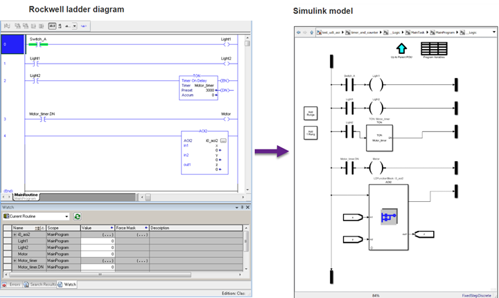
With Simulink® PLC Coder™, you can use ladder import to import ladder diagrams created with Rockwell Automation® IDEs, such as RSLogix™ 5000 and Studio 5000 into the Simulink environment as a model. You can create ladder diagrams in the Simulink environment as a model.
After importing or creating the ladder diagram models, you can:
Edit the imported Ladder Diagram model from within Simulink by using the
plcladderliblibrary.After importing the ladder diagram code into Simulink, simulate it.
Generate C code from the imported ladder diagram and integrate the code into your existing C language-based simulation environments.
Generate ladder diagram code from the imported ladder diagram and integrate the code into your Rockwell Automation IDE. You cannot generate structured text code from the Ladder Diagram blocks.
Generate PLC testbench code for the imported ladder diagram and verify the code in your Rockwell Automation IDE.

Apps
| Simulink PLC Coder | Generate structured text and ladder diagram code from Simulink models, Stateflow charts, and MATLAB functions (Since R2019b) |
Functions
Blocks
Topics
- Supported Elements in Ladder Diagram
Ladder features and elements that are supported by Simulink PLC Coder.
- Import L5X Ladder Diagram Files into Simulink
Import L5X ladder diagram files into Simulink.
- Model and Simulate Ladder Diagrams in Simulink
Create and simulate ladder Diagrams in Simulink.
- Generating Ladder Diagram Code from Simulink
Generate Ladder Diagram code (L5X) from Simulink.
- Generating C Code from Simulink Ladder
Generate C code from a Simulink Ladder Diagram Model.
- Verify Generated Ladder Diagram Code
Verify generated code against the original Simulink model in your IDE using a generated test bench.
- Create Custom Instruction in PLC Ladder Diagram Models
Create user-defined instruction in PLC Ladder Diagram models.


