Developing the World’s Most Advanced Prosthetic Arm Using Model-Based Design
By James Burck, Johns Hopkins University Applied Physics Laboratory, Michael J. Zeher, Johns Hopkins University Applied Physics Laboratory, Robert Armiger, Johns Hopkins University Applied Physics Laboratory, and James D. Beaty, Johns Hopkins University Applied Physics Laboratory
Few of us are aware of the complex interactions between neural, mechanical, and sensory systems required to perform a task as simple as picking up a ball. To create a prosthetic arm capable of natural movement, it is necessary to mimic these sophisticated systems, as well as the intricate interactions between them, using cutting-edge actuators, sensors, microprocessors, and embedded control software. That was the challenge we faced when we embarked on the Defense Advanced Research Projects Agency (DARPA) Revolutionizing Prosthetics program.
Johns Hopkins University Applied Physics Laboratory (APL) is leading a worldwide team including government agencies, universities, and private companies whose mission is to develop a prosthetic arm that far exceeds any prosthetic available today. The final version of the arm will have control algorithms driven by neural inputs that enable the wearer to move with the speed, dexterity, and force of a real arm. Advanced sensory feedback technologies will enable the perception of physical inputs, such as pressure, force, and temperature.
A key project milestone was the development of the Virtual Integration Environment (VIE), a complete limb system simulation environment built using MathWorks tools and Model-Based Design. With a standardized architecture and well-defined interfaces, the VIE is enabling collaboration among domain experts at more than two dozen partner organizations.
Model-Based Design with MathWorks tools was used in other key phases of development—including modeling the limb mechanics, testing new neural decode algorithms, and developing and verifying control algorithms.
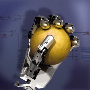
Virtual Integration Environment Architecture
The VIE architecture consists of five main modules: Input, Signal Analysis, Controls, Plant, and Presentation.
The Input module comprises all the input devices that patients can use to signal their intent, including surface electromyograms (EMGs), cortical and peripheral nerve implants, implantable myoelectric sensors (IMESs) and more conventional digital and analog inputs for switches, joysticks, and other control sources used by clinicians. The Signal Analysis module performs signal processing and filtering. More important, this module applies pattern recognition algorithms that interpret raw input signals to extract the user’s intent and communicate that intent to the Controls module. In the Controls module, those commands are mapped to motor signals that control the individual motors that actuate the limb, hand, and fingers.
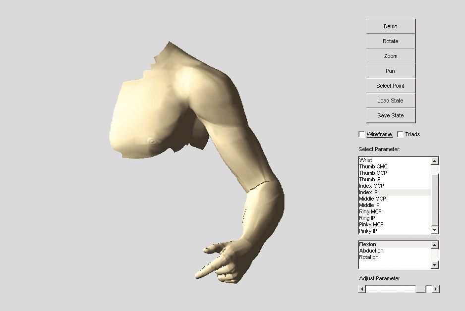
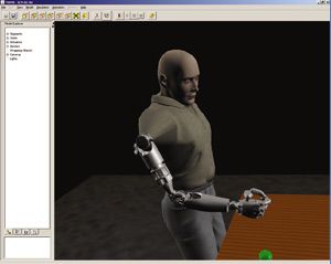
The Plant module consists of a physical model of the limb’s mechanics. The Presentation module produces a three-dimensional (3D) rendering of the arm’s movement (Figure 1).
Interfacing with the Nervous System
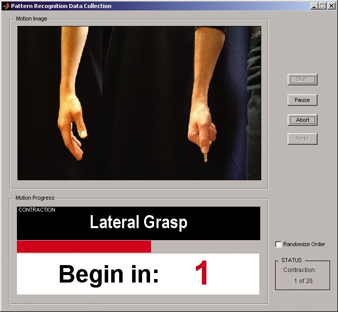
Simulink® and the VIE were essential to developing an interface to the nervous system that allows natural and intuitive control of the prosthetic limb system. Researchers record data from neural device implants while the subjects perform tasks such as reaching for a ball in the virtual environment. The VIE modular input systems receive this data, and MATLAB® algorithms decode the subject’s intent by using pattern recognition to correlate neural activity with the subject’s movement (Figure 2). The results are integrated back into the VIE, where experiments can be run in real time.
The same workflow has been used to develop input devices of all kinds, some of which are already being tested by prosthetic limb users at the Rehabilitation Institute of Chicago.
Building Real-Time Prototype Controllers
The Signal Analysis and Controls modules of the VIE form the heart of the control system that will ultimately be deployed in the prosthetic arm. At APL, we developed the software for these modules. Individual algorithms were developed in MATLAB using the Embedded MATLAB™ subset and then integrated into a Simulink model of the system as function blocks. To create a real-time prototype of the control system, we generated code for the complete system, including the Simulink and Embedded MATLAB components, with Real-Time Workshop®, and deployed this code to xPC Target™.
This approach brought many advantages. Using Model-Based Design and Simulink, we modeled the complete system and simulated it to optimize and verify the design. We were able to rapidly build and test a virtual prototype system before committing to a specific hardware platform. With Real-Time Workshop Embedded Coder™ we generated target-specific code for our processor. Because the code is generated from a Simulink system model that has been safety-tested and verified through simulation, there is no hand-coding step that could introduce errors or unplanned behaviors. As a result, we have a high degree of confidence that the Modular Prosthetic Limb will perform as intended and designed.
Physical Modeling and Visualization
To perform closed-loop simulations of our control system, we developed a plant model representing the inertial properties of the limb system. We began with CAD assemblies of limb components designed in SolidWorks® by our partners. We used the CAD assemblies to automatically generate a SimMechanics™ model of the limb linked to our control system in Simulink.
Finally, we linked the plant model to a Java™ 3D rendering engine developed at the University of Southern California to show a virtual limb moving in a simulated environment.
Clinical Application
Given the powerful virtual system framework, we were also able to create a useful and intuitive clinical environment for system configuration and training. Clinicians can configure parameters in the VIE and manage test sessions with volunteer subjects using a GUI that we created in MATLAB (Figure 3).
Clinicians interact with this application on a host PC that communicates with the xPC Target system running the control software in real time. A third PC is used for 3D rendering and display of the virtual limb. During tests of actual limbs, we can correlate and visualize control signals while the subject is moving.
Looking Ahead
Using Model-Based Design, the Revolutionizing Prosthetics team has delivered Proto 1, Proto 2, and the first version of the VIE ahead of schedule. Currently we are in the process of developing a detailed design of the Modular Prosthetic Limb, the version that we will deliver to DARPA.
Many of our partner institutions use the VIE as a test bed as they continue to improve their systems, and we envision the VIE continuing as a platform for further development in prosthetics and neuroscience for years to come. Our team has established a development process that we can use to rapidly assemble systems from reusable models and implement on prototype hardware, not only for the Revolutionizing Prosthetics project but for related programs as well.
As we meet the challenge of building a mechatronic system that mimics natural motion, we strive to match the perseverance and commitment that our volunteer subjects and the amputee population at large demonstrate every day.
Approved for Public Release, Distribution Unlimited.
Mimicking Nature on a Deadline
Developing a mechatronic system that replicates natural motion and preparing it for clinical trials in just four years, as mandated by DARPA, requires breakthroughs in neural control, sensory input, advanced mechanics and actuators, and prosthesis design.
State-of-the-art prosthetic arms today typically have just three active degrees of freedom: elbow flex/extend, wrist rotate, and grip open/close. Proto 1, our first prototype, added five more degrees of freedom, including two active degrees of freedom at the shoulder (flexion/extension and internal/external rotation), wrist flexion/extention, and additional hand grips. To emulate natural movement, we needed to go far beyond the advances in Proto 1.
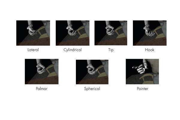
Proto 2, which was developed as an electromechanical proof of concept, had more than 22 degrees of freedom, including additional side-to-side movements at the shoulder (abduction/adduction), wrist (radial/unlar deviation), and independent articulation of the fingers. The hand can also be commanded into multiple highly functional coordinated “grasps.”
The Modular Prosthetic Limb—the version that we will deliver to DARPA—will have 27 degrees of freedom, as well as the ability to sense temperature, contact, pressure, and vibration.
Published 2009 - 91782v00
